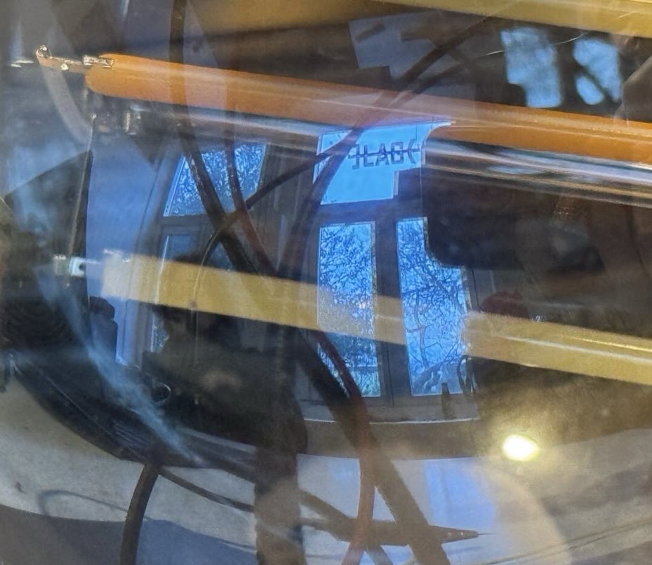
Lightbulb hacking: How to make a web server from a smart light bulb?
]LAG( hacklab reflected in the bulb (enlarge):

NB: Companion page to the permaculture chapter!
This page is about making a web server from a smart light bulb. The rationale is laid out in an article we are writing for a collected volume. The practical steps are detailed here.
| Table 1 | Basic information about the product and hack |
|---|---|
| Make | LSC |
| Model | 970739 |
| Sold online | https://shop.action.com/en-nl/p/8712879146605/lsc-smart-connect-led-bulb-white |
| App link | https://play.google.com/store/apps/details?id=com.lscsmartconnection.smart&hl=en_US |
| Vendor instructions | https://www.youtube.com/watch?v=MEXBVvQxZCo |
| Similar product in EU database | https://eprel.ec.europa.eu/screen/product/lightsources/1421108 |
| Microcontroller | ESP8285, a heat resistant version of ESP8266 with extra memory. |
| Datasheet | https://www.espressif.com/en/products/hardware/esp8266ex/overview |
| Tutorial | https://randomnerdtutorials.com/esp8266-web-server/ |
| Howto | https://www.instructables.com/How-to-Get-Started-With-ESP8285-Module-/ |
| Alternative firmware | https://github.com/RuiSantosdotme/Random-Nerd-Tutorials/raw/master/Projects/ESP8266_Web_Server_Arduino_IDE_updated.ino |
| Our code | https://git.puscii.nl/lag/lightbulb-webserver |
Note: At the time of writing the product was already sold out in Action stores. It seems that these cheap light bulbs do not spend much time on the shelves. There must be new versions coming out. Perhaps similar ones can be found online on in your local hardware store.
Contents
- Step 0: Choose a suitable smart light bulb product
- Step 1: Take the light bulb apart
- Step 2: Identify the microcontroller inside the light bulb
- Step 3: Wiring up the microcontroller to a computer
- Step 4: Flashing firmware to the microcontroller
- Step 5: Accessing the website on the light bulb
- Step 6: Iterating over the process
- Step 7: Ideas for repurposing
Step 0: Choose a suitable smart light bulb product
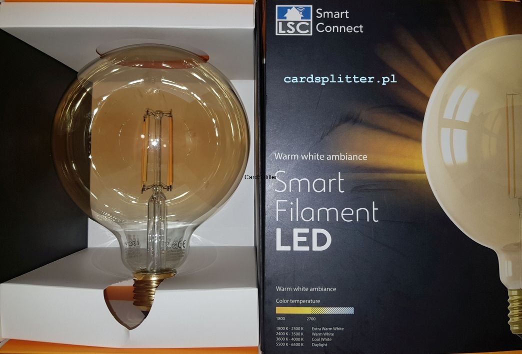
We were looking for popular products that are easy to find on the shelves of hardware stores in the Netherlands. We tried a few and dissected on in the second hacking session. In the third hacking session we realised that the LSC 970739 is a more accessible one, because it is easier to reach the right pins on the chip inside and there is already open source firmware to operate a a web server on it. These smart light bulbs are widely available at the Action stores.
Product image from cardsplitter.pl (enlarge):

Diagram of the supply chain (PDF or DOT):

Step 1: Take the light bulb apart
You will need the following tools: - a hot air gun - an oven mitten or some other heat-resistant thing to protect your hand - a vice (or something else to hold the light bulb in) - most bulb sockets are made of plastic and so if you try to use that you're likely to melt them. Unless you have one of those old-school ceramic ones from your great grandparents era. Then it's fine. - a small flathead screwdriver or other picking-scraping tool - a soldering iron and desoldering wick - a pry tool (could be the same screwdriver you use for scraping) - to take the board out of the metal socket.
Place the bulb in a vice to hold the bottom part. Don't overtighten - once the glue is heated up you don't need to use that much force to take it out. Then heat up the glass (not the metal) aiming at the bottom part of the bulb. (enlarge)

We used the low heat setting on the glue gun and it took about 3 minutes, be patient. Try moving the heat gun around the bulb to heat it evenly. While doing this, keep wiggling the bulb with your protected hand - at some point it will actually start wiggilng and then you can take it off. (enlarge)

You should bee able to see this board (enlarge)

Next, you will have to scrape the remaining foam/glue off. The foam is gonna be hardened and it will take you a while to remove. You don't need to make it totally clean, just make sure the board is not stuck to the socket anymore. (enlarge)

You can start desoldering. You'll have to desolder the live and neutral cables that go to the case first and take the board out of the socket. The pads are next to each other. This is best done by sucking up all the solder possible from the pads in question, then pulling on the wire that's soldered to the socket (neutral) and then simultaneously heating up the pad and prying it away to pull the live cable out. The solder pads where these cables are attached contain 2 vias each - one for the cable we're trying to desolder and the other one for a foil capacitor that's soldered accross live and neutral. The capacitor does not need to be removed. The picture below this section pictures which pads are live (brown) and neutral (blue) (enlarge)

Once that's done removing the chewing gum-like goop protecting the board and don't lose it, it is isolation material and you should put it back when reassembling.
Last step is removing the electrolytic capacitor that prevents access to the board that our microcontroller is on. This is marked with green arrows on the picture below. (enlarge)

Step 2: Identify the microcontroller inside the light bulb
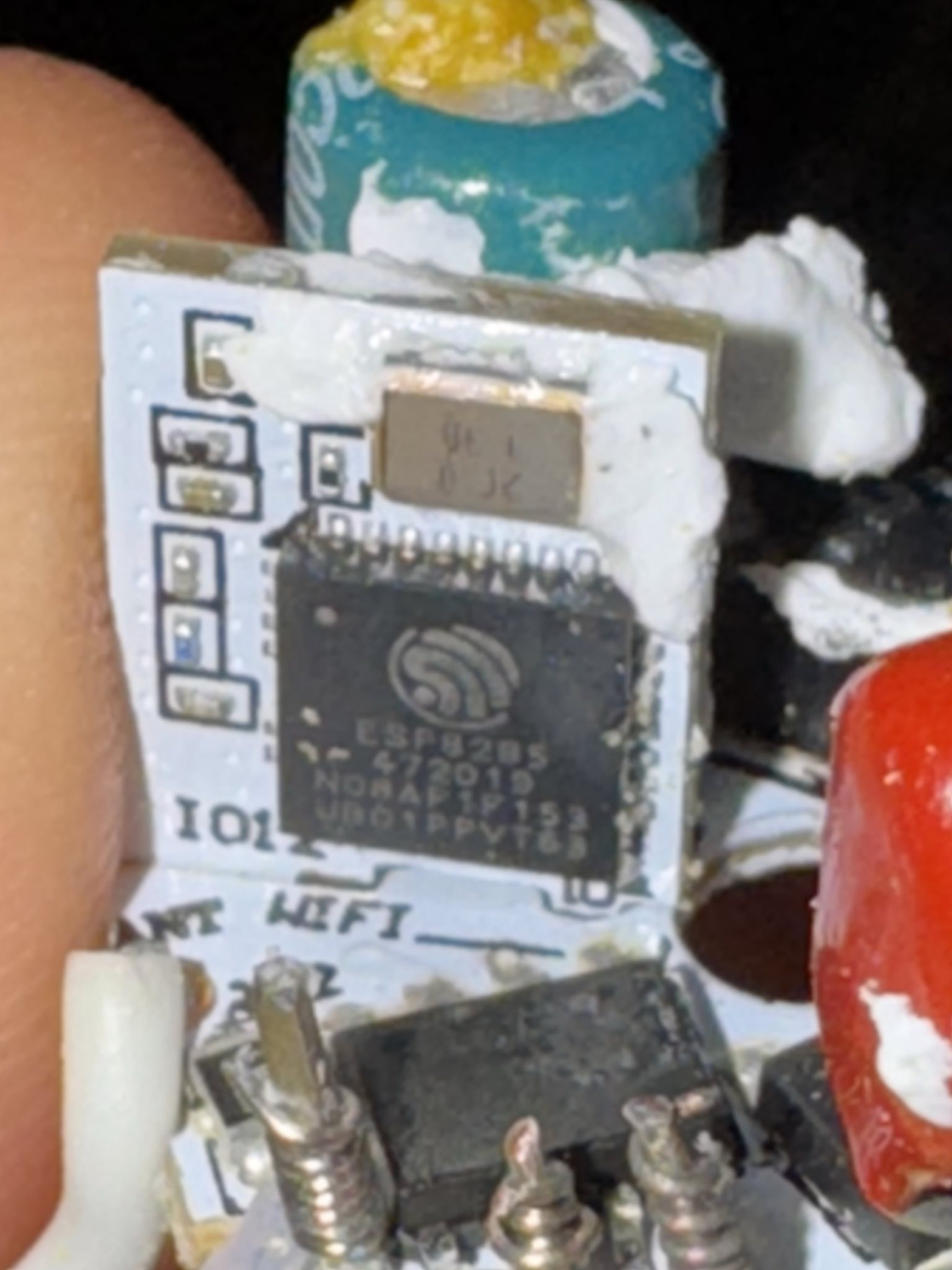
Photo of the microcontroller (enlarge):
Opening up the case reveals the microcontroller.

The numbers on the surface of the chip are the following:
- ESP8285
- 472019
- MDRAP1F153
- UBIO1PPVT63
The ESP8285 microcontroller is a very capable chip, especially for a light bulb — probably more powerful than the computers that brought humans to the moon for the first time:
ESP8285 = ESP8266 + 1M Flash, so that it can withstand high temperatures up to 125 degrees Celsius! And the original ESP8266 source code program can be used to transplant. ESP-M3 module core processor using cost-effective chip ESP8285. The chip integrates the enhanced version of the Tensilica's L106 Diamond 32-bit core processor with on-chip SRAM in a smaller package. ESP8285 has a complete Wi-Fi network function, both can be used independently, can also be used as a slave from other host MCU running. When the ESP8285 hosting application, can be started directly from the external Flash. Built-in cache memory facilitates system performance and optimizes storage systems. In addition, ESP8285 only through the SPI / SDIO interface or I2C / UART port can be used as a Wi-Fi adapter, applied to any microcontroller-based design. — https://www.instructables.com/How-to-Get-Started-With-ESP8285-Module-/
It's still a bit difficult to access the chip, especially without specialist tools like PCbite. Fortunately, we do have PCbite here. A lab power supply is also useful to see what the light bulb is doing and how much energy it consumes, but it is also perfectly fine to power the bulb from an USB-to-UART cable (see diagram below).
Step 3: Wiring up the microcontroller to a computer
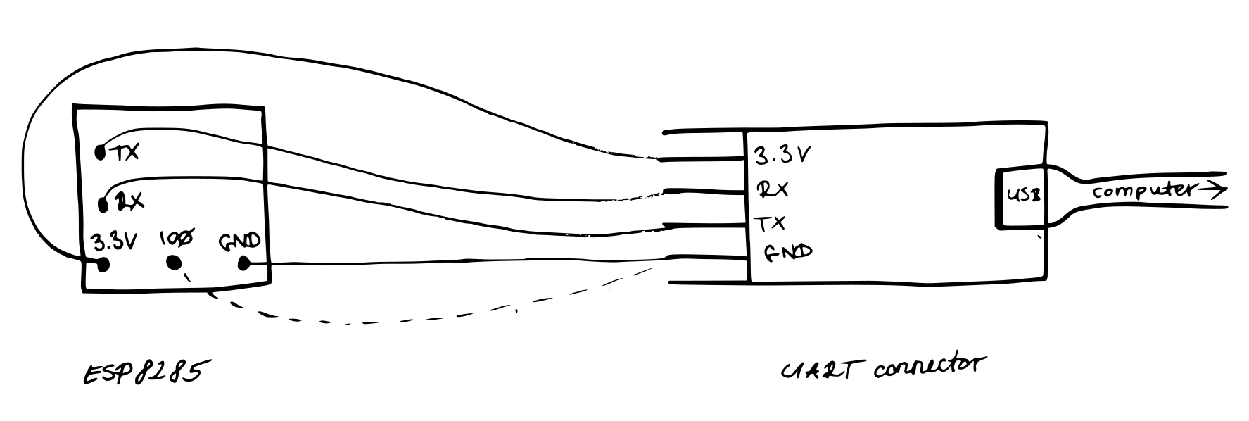
The setup includes a UART-to-USB controller, which translates between the microntroller and the computer, so that they can talk to each other.
Diagram of the wire-up (enlarge):

Actual view (enlarge]:
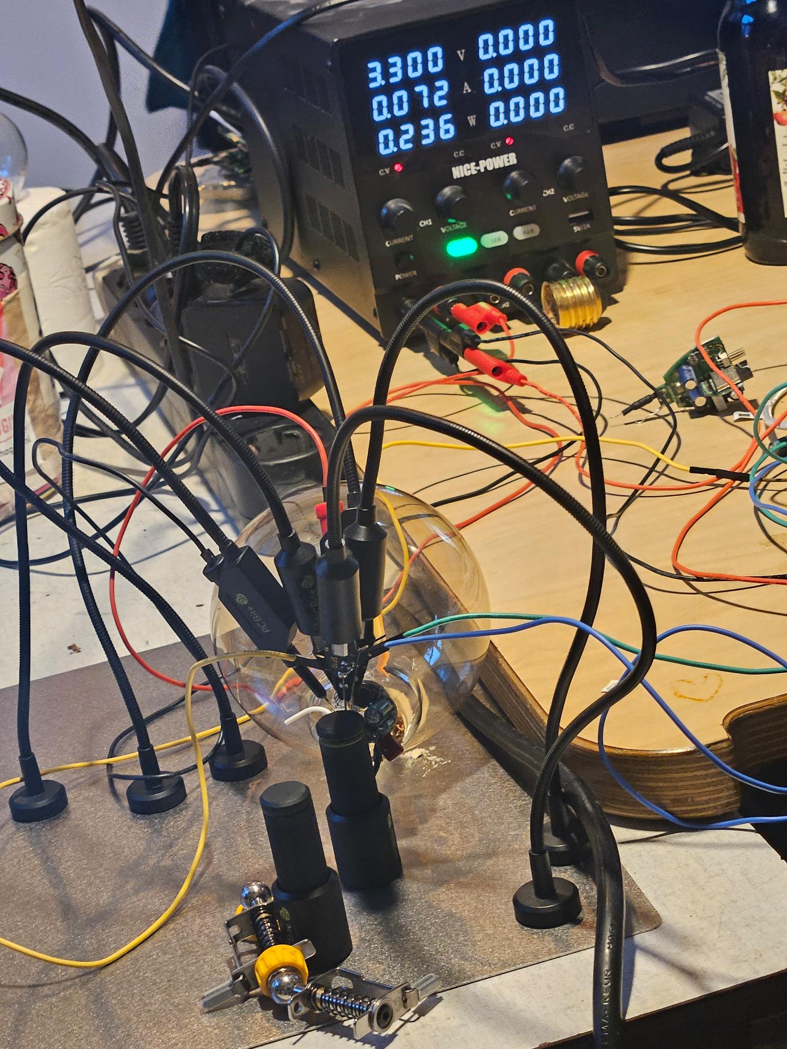

Step 4: Flashing firmware to the microcontroller
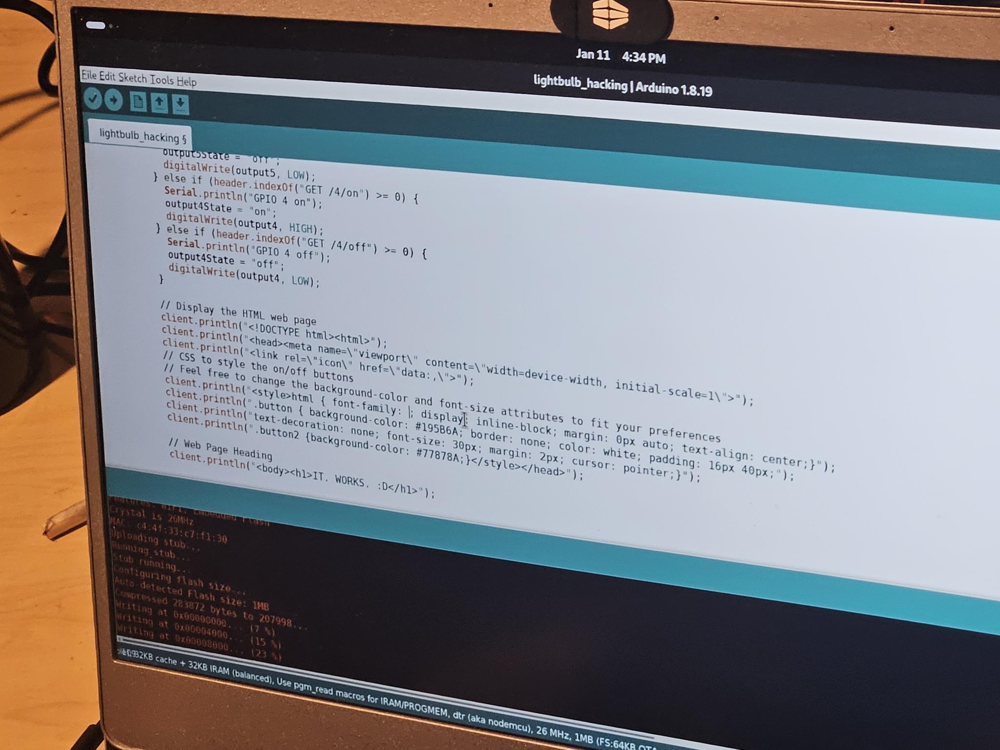
There are number of variables that need tweaking in order to make the alternative webserver firmware work as intended. The two important ones are in the third paragraph of the code: the name and password for the WiFi network that the light bulb will connect to. These depend on what local WiFi network you have available. Replace "REPLACE_WITH_YOUR_SSID" with the name of your WiFi network and put the password in the place of "REPLACE_WITH_YOUR_PASSWORD“.
Arduino IDE works to flash the firmware.
Using the Arduino IDE to edit the code (enlarge]

Step 5: Accessing the website on the light bulb
The website is accessible after connecting to the WiFi network of the bulb and navigating with a web browser to the IP address of the microntroller.
Accessing the website on the bulb (enlarge):
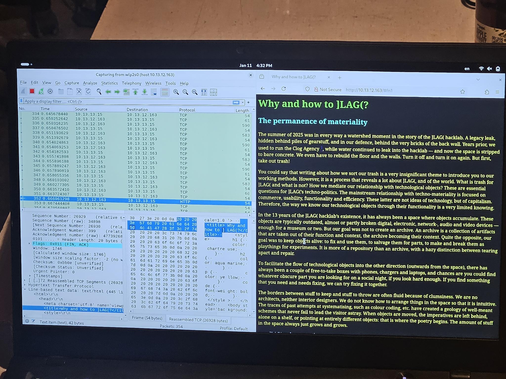

| Table 2 | ]LAG( bulbserver settings |
|---|---|
| Microcontroller IP | 10.13.12.163 |
| Website address | http://10.13.12.163/ |
Optionally, Wireshark can show the network traffic between the client (computer/mobile) and the light bulb web server (see left side of the image above).
Optionally, in the Aduino IDE prints the web server logs to the debug console while the light bulb is connected with the UART-to-USB cable.
Step 6: Iterating over the process
Repeating the process, making more lightbulbs, tweaking the code and the contents are all logical options here. We have adapted the code to display the chapter draft for the permacomputing book that is mentioned in the beginning of this page. The relevant part of the code starts here:
//Display the HTML web page
The actual lines of the content are printed one by one (or you can just make them one long line):
client.println("Your line here");
The page we rendered is here and the code the webserver code that renders it is here.
Step 7: Ideas for repurposing
The datasheet of the microntroller and the tutorial cited above has a list of technical features such as communication protocols, sensors and actuators that the chip has, most of which are available for programming from the firmware.
There were ideas floating around about how to make the smart light bulb more interactive. For example we could change the colour if we get messages from the upstairs neighbours that we are too noisy. Or it could flash when a new message arrives to a chat, or turn on when the hacklab is open. However, the point of this exercise is not to engage in home automation practices, but exactly to show how absurd it is that nowadays even lightbulbs have general purpose computers — and therefore critical natural resources — built into them!
References
Permacomputing wiki:
Etherpads with some of the notes:
Event announcements on radar.squat.net: